I have since first finding out about it in 2012 been interested in aquaponics. It captured my imagination because exemplifies the adaptability of living systems. Plants, fish, bacteria, nutrients, water, air, and energy all in a single cycle. The benefits of this technology include sustainable (low water use and low pollution) crop production and fish farming. While at the University of Waterloo I had the opportunity to work on three aquaponic systems with the Aquaponics Design Team. This is a summarized account of the work we did what we learned.
System 1
The first UW Aquaponics system was a proof of concept system built a few years before I joined the team and was continued as a legacy system. It underwent a few modifications but was an inexpensive flood and drain system that had an aquarium, sump tank, and hydroponic tank filled with expanded clay.
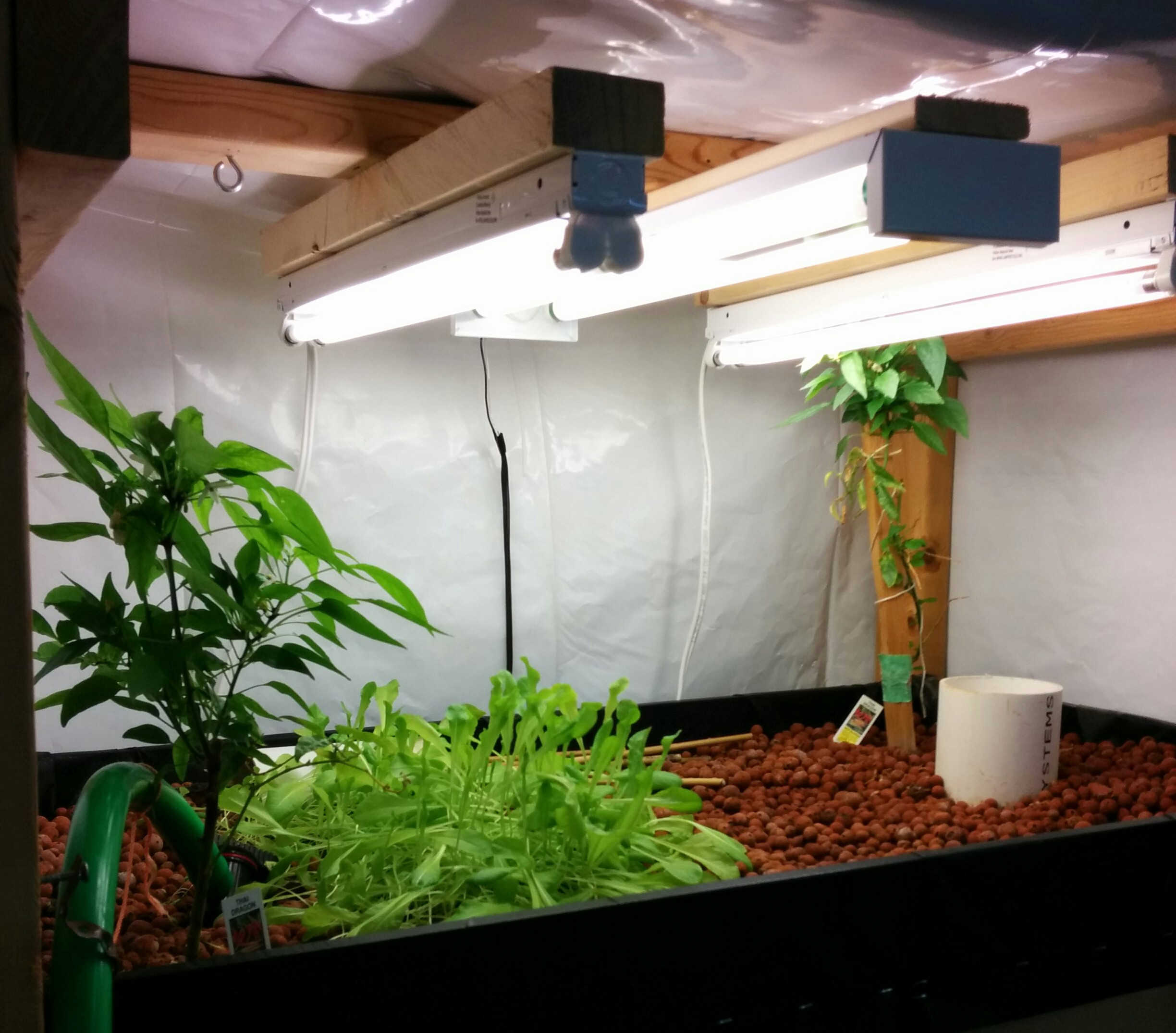
The water traveled from the fish tank to the sump tank (this balanced the water level change from the flood and drain hydroponic tank) then was pumped up to the grow bed (see figure below 2) where the plants would uptake the nitrate and other nutrients. Finally the water would be drained to the fish tank and be aerated.
Issues: lighting, water hardness, and biomass
The lighting was originally only two 3-foot fluorescent tubes. The lux (lumens per square meter) at the plant level was only around 2000-3000 and not nearly enough for anything to thrive. Eventually we added four additional 2-foot fluorescent fixtures and the lux at plant level went up to around 8,000-10,000. We chose fluorescent tubes with a higher colour temperature because these produce more blue light, which is crucial for vegetative growth.
After a several years of operation the system had many calcium deposits from the hard Waterloo tap water we were using, but this denoted a larger problem. The water was too basic for the plants. With the pH near 8 we weren't growing much. We decided the best way to solve this issue was to use a reverse osmosis filter for the system water (see figure below).
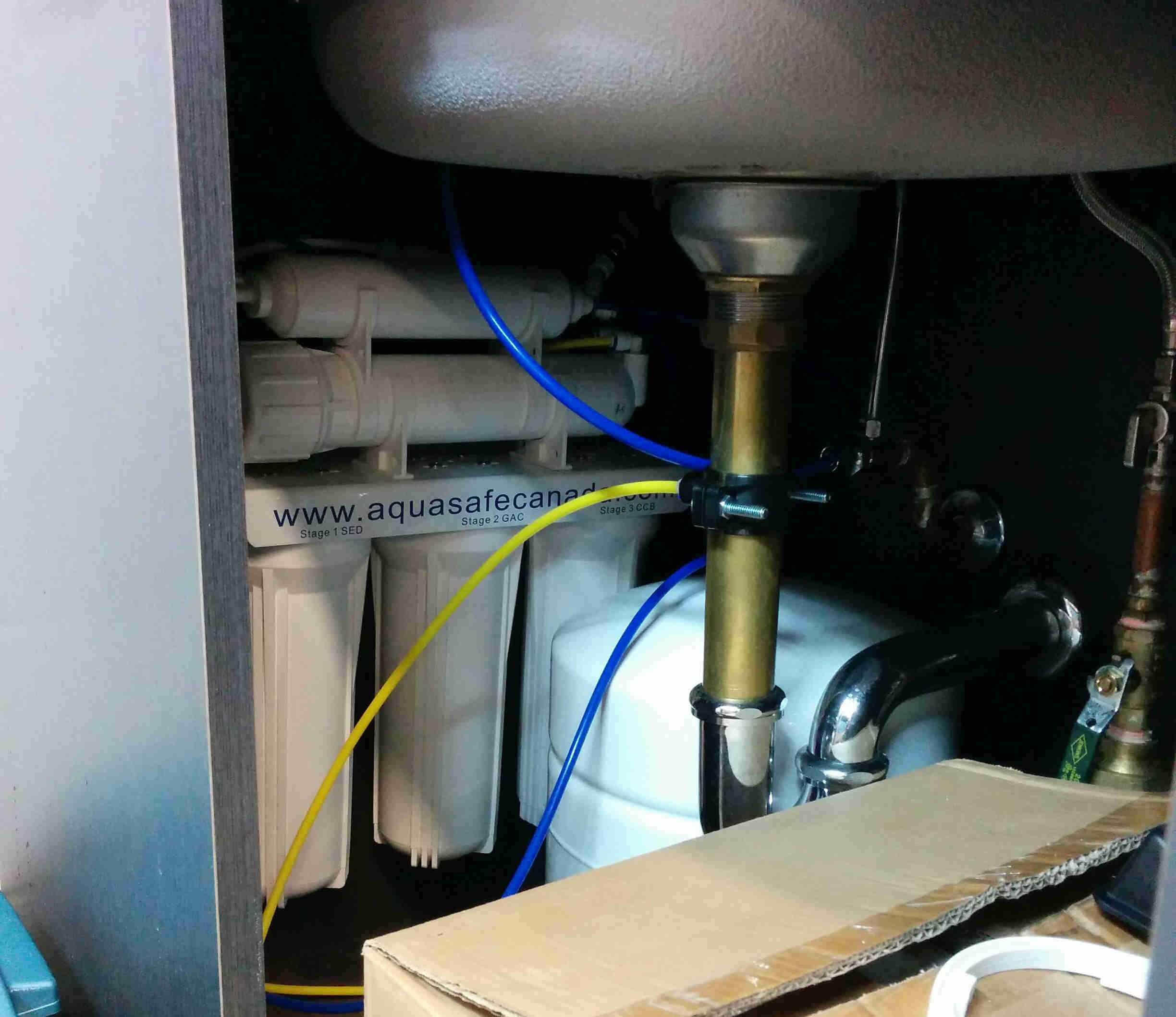
The reverse osmosis filter tapped into the drinking water pipe to the sink in the lab and produced water that had extremely low total dissolved solids. The water was filtered very slowly so it took a long time to accumulate even 1 liter, but because such little water is used by the system this was not an issue.
Lastly, having only a few fish reduced the amount of nutrients available for the plants. However, because the aquarium tank was small adding more fish wasn't possible.
Conclusion: The balance between: plant growth area, and plant lighting, water quality, fish biomass, and fish tank volume needs to be correct.
System 2
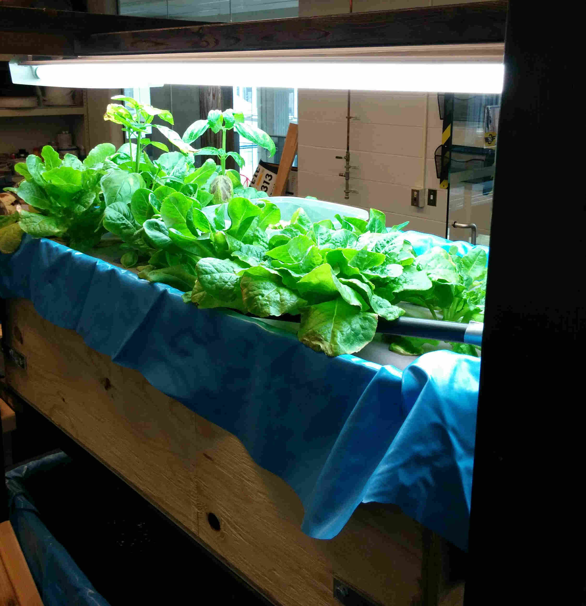
System 2 was designed to be a mobile aquaponics book shelf that we could wheel around for demonstrations on campus. It consisted of a: fish tank, biofilter, hydroponic tank, light fixture, pump, air blower, tubing, and wooden frame on casters. (see figure below).
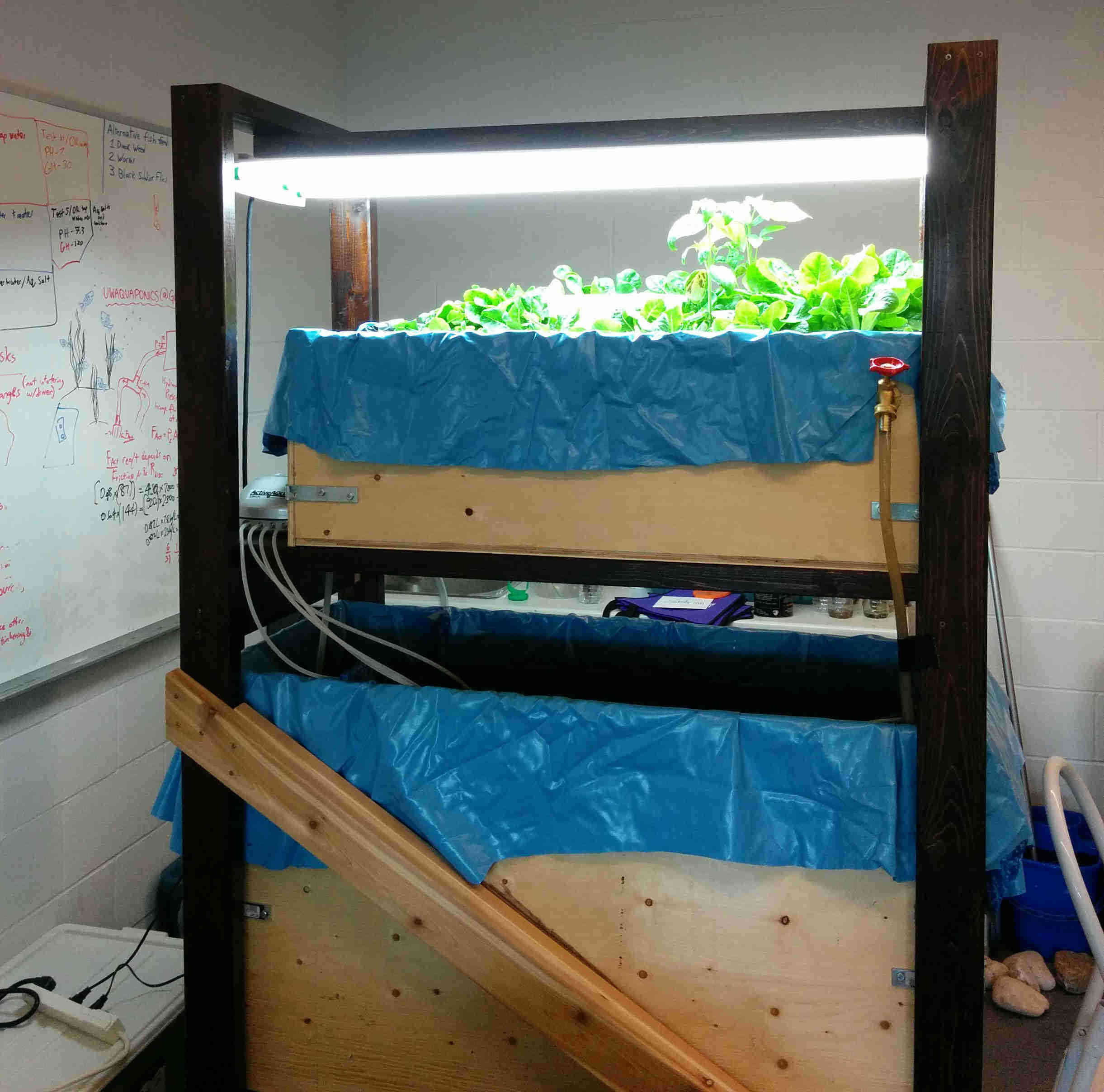
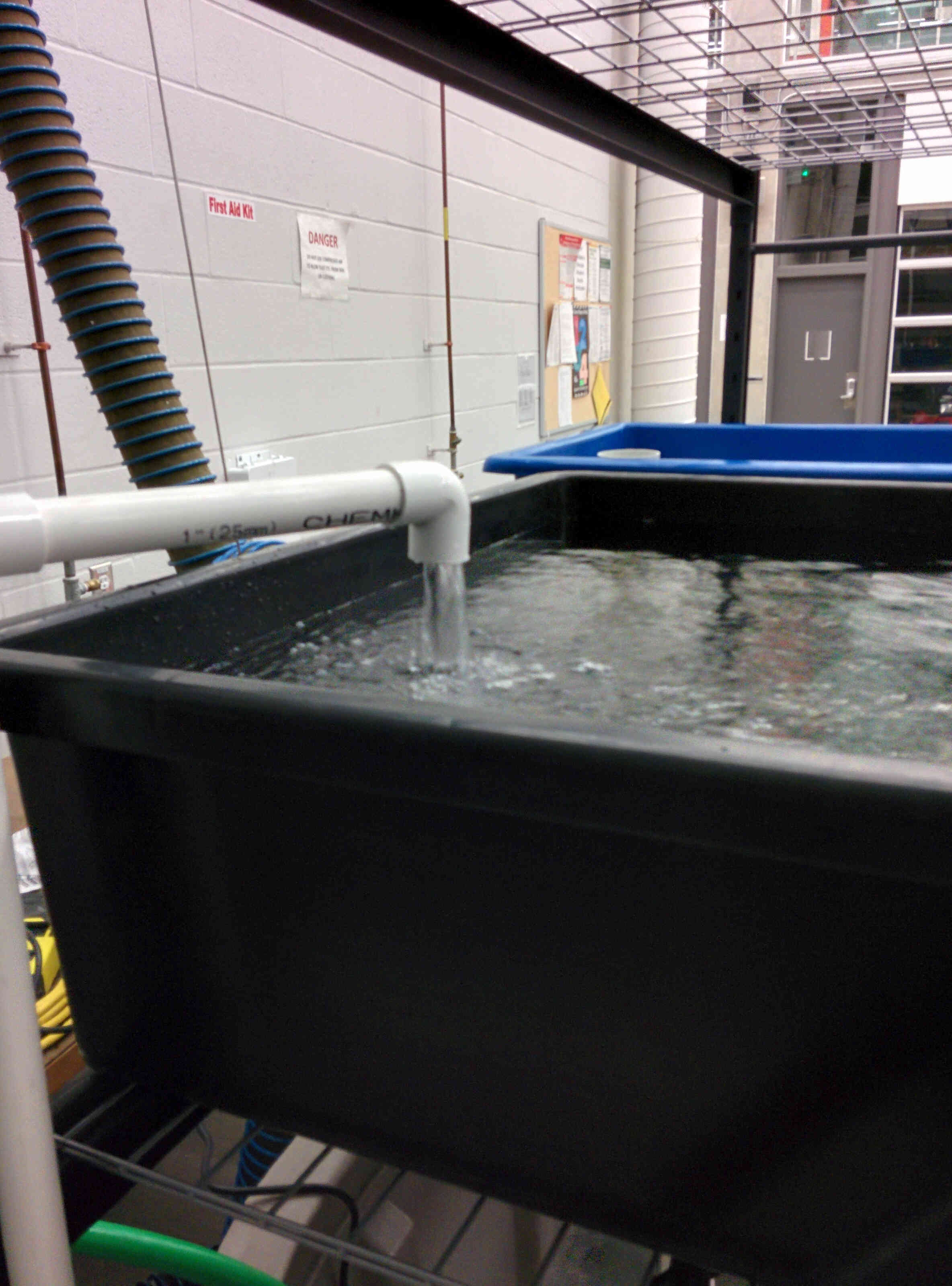
The water traveled from the fish tank to the biofilter (which was a compartment in the lower tank that was filled with expanded clay pellets) then was pumped up to the deep water hydroponic tank where the plants (siting in mesh pots on a floating raft) would uptake the nitrate and other nutrients. Finally the water would be drained to the fish tank and be aerated.
Issue: custom built tanks
I thought it would be cheaper to create a custom polyethylene (PE) tank from 3 mm sheets. This was not easy work. I tried special adhesives, epoxy, solvents, and caulking to get a strong seal on it with no success. We even tried hot air plastic welding which was slow, difficult, and unwieldy. After abandoning this idea we went with pond lining plywood boxes made using bolted angle brackets. The water pressure caused the plywood to bow on the larger tank so we reinforced it with cross bracing from the wooden frame. This worked relatively well but the lining still had large folds that didn't get adequate water circulation. In any case this tank would not last a long duration in use (though that wasn't of great importance for our design).
Conclusion: buy a rugged premade tank. We could have reworked the frame design to fit one but choose to do the opposite. Big mistake.
System 3
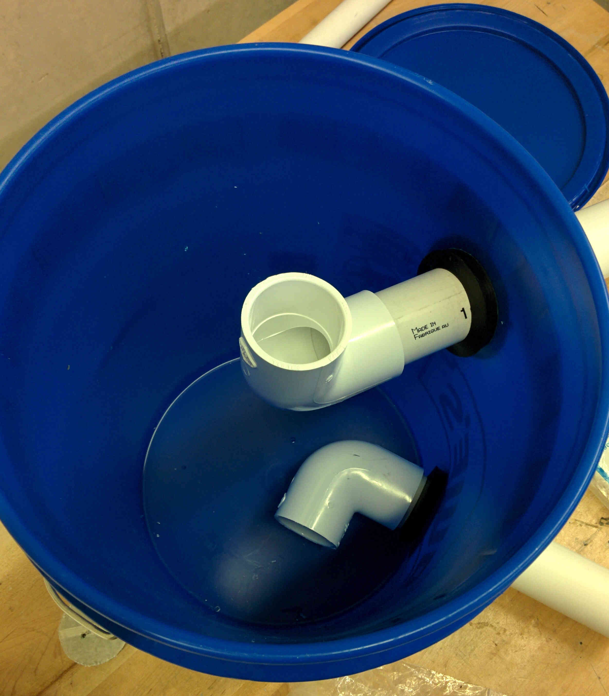
This system was designed for modularity and ease of assembly. It had to fit into a lab space provided in the Aquatic Animals Research Facility on campus and be disassembled for transport to demonstrations off campus. We used premade plastic tanks and steel racking and a swirl filter for solid waste made from a food safe bucket (see figure 8 below).
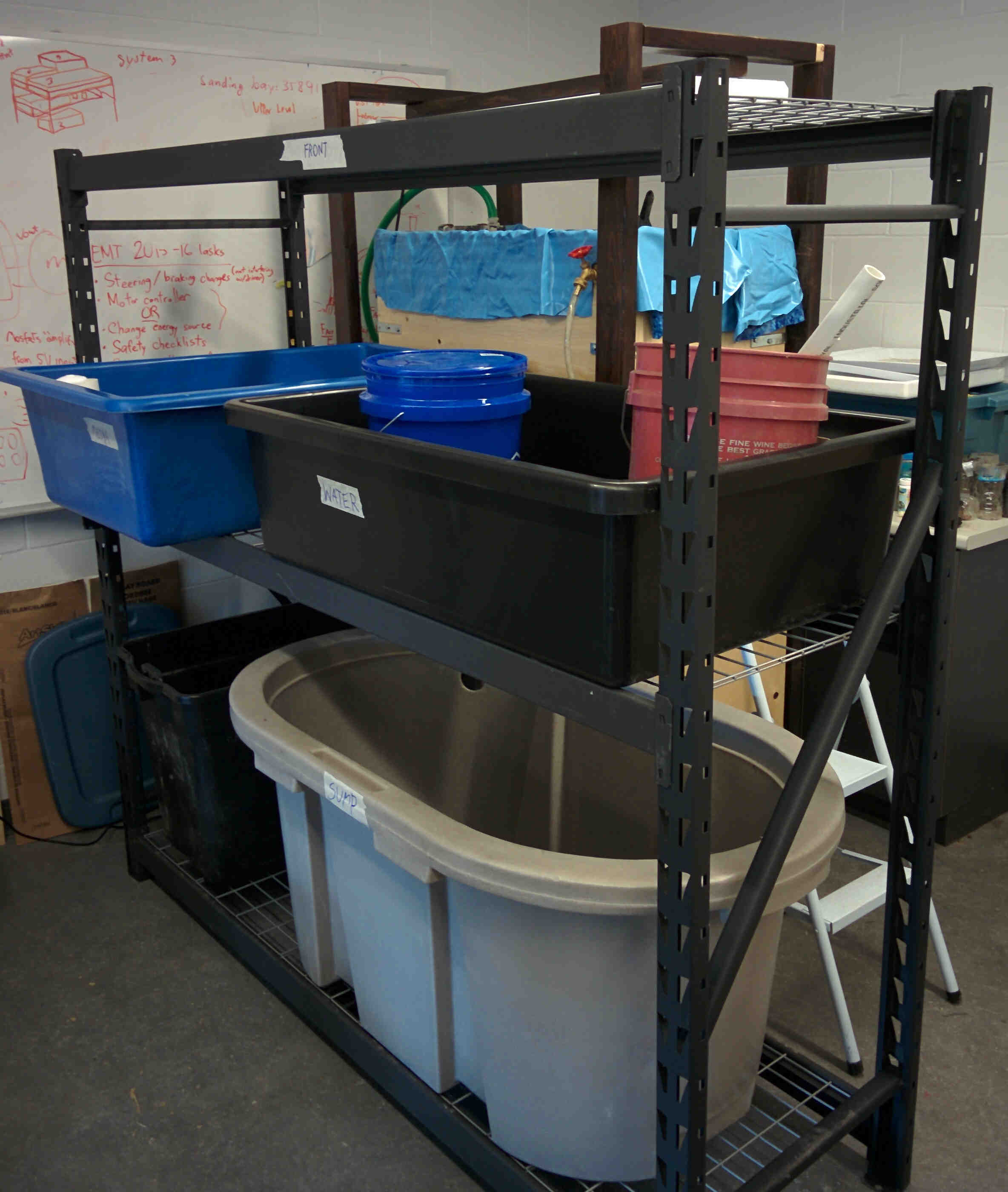
The two upper hydroponic tanks were to be one deep water culture and one flood and drain (with bell siphon) to show the difference between techniques. We installed the pipe fittings and connections but found that assembly was more difficult than imagined.
Issue: pipe fittings
Uniseals require substantial elbow grease to install correctly which made the swirl filter construction take much longer than anticipated. The pressure fit coupling between the two grow beds was the larger issue though because it had to be removed for disassembly and it was in an awkward place to pull apart. We would have to take the bulkhead seals off for this, which was not ideal. We replaced this coupling with a threaded coupling that was much easier to disassemble and used threaded couplings throughout the rest of the system.
Conclusion: think more about the couplings and general assembly work. A sturdy simple design that can be easily serviced goes a long way.